Authors: Mark Clymer
1, Kieran Slicker
2 and Ed Balcerzak
1
1UNITRON Ltd., Commack, NY (http://www.unitronusa.com)
2Ash Technologies, Naas, Ireland (http://ash-vision.com)
Originally published by Mid-Atlantic Tech Publications, Inc., May 2018:
http://us-tech.com/RelId/1966467/ISvars/default/What_s_Next_for_Visual_and_Optical_Inspection_.htm
The need to inspect and ensure circuit board integrity is of great consideration, but what system is best for this purpose? It is not a simple question to answer since the requirements of the application, work environment and sample must be the primary determining factors. Additionally, where traditional inspection systems may have been sufficient, advances in manufacturing technology may dictate the need for more sophisticated inspection instruments.
When a little can be enough of a good thing
Magnifiers were the first tools to aid in assembly and inspection of circuit boards. Not much more advanced than a magnifying lens on an arm, magnifiers are comprised of a simple lens, and are a logical choice where a low level of magnification is needed to perform soldering, and to observe and inspect solders and other features in the sample. If the sample when seen through a magnifier is satisfactory, will more magnification necessarily be better?
Magnifiers are available as fixed magnification that is rated in diopters. Diopter roughly translates to power or the magnification factor of the magnifier, where a higher diopter rating equates to higher magnification. A simple calculation can be used to determine the magnification power is of a magnifier: simply divide the diopter factor by 4, then add 1. For example, a 3-diopter lens on a magnifier gives a magnification power of ¾ + 1 = 1.75x. A 4-diopter has a magnification power of 2x, and a 5-diopter has a magnification power of 2.25x.
When the components or detail of the sample get smaller, the solution is to buy magnifiers with higher diopters, right? Not so fast. Diopters also have a relationship to working distance. The working distance is the optimal distance a magnifier needs to be from the sample for best viewing – this is similar to focal length. So, the higher the diopter, the shorter the working distance and the closer the magnifier needs to be to the sample. A 3-diopter has a working distance of 13 inches – plenty of room for hands and tools. By contrast, a 5-diopter has a working distance of 8 inches, and the working distance of an 11-diopter shrinks to 3.75 inches – barely enough room to safely place a board under the magnifier.
So how much magnification is really needed? Well that depends on the task and, as was just discussed, the working distance that allows the work to be done safely.
Shining a light on inspection
Good lighting goes far beyond just having some overhead lights in the shop. Shadows can lead to poor assembly production, higher rejection rates, and missed flaws during inspection. Magnifiers can be purchased with integrated illumination, but supplementary illumination or task lighting often enhance the operator’s performance.
The type of illumination can, and should, be a consideration. While incandescent or halogen lighting were the original gold standards, fluorescent lighting became the norm for decades. Now, new LED sources offer attractive options for task lighting. However, LED illumination is not all the same. Some LED lights appear “bluer” or colder compared to others, and some appear “yellower” or warmer. Halogen and incandescent light intensity can be readily increased or decreased as needed, and the appearance of the light changes with the voltage giving a whiter light at their brightest, and yellower light as they are dimmed. On the other hand, LEDs maintain their color cast across the intensity range. It’s best to try the different types of illumination to determine which provides the best contrast for the work being done.
Heat may pose a concern, too, when working with task lighting for prolonged periods. Halogen lights heat up more quickly than fluorescent and LED, and have a shorter life span. LEDs can last for 50,000 hours or more, and don’t generate much heat – fluorescent lights fall somewhere in between. In any respect, it is important to choose lighting that is comfortable on the eyes to both reduce fatigue and improve visibility of the component being observed or inspected, even when using tools.
Stereo microscopes
Where higher magnification is needed, stereo microscopes (“stereos” for short) are a logical choice. Magnifiers have one optical path, and operators still benefit from binocular vision to preserve a sense of depth of the sample. Stereo microscopes feature two optical paths, one for each eye, and they are designed to deliver a similar 3D experience as magnifiers, even at higher magnifications.
Stereo microscopes come in two general flavors of magnification – fixed and zoom. Where a single magnification is needed and sufficient, a fixed magnification stereo microscope (“fixed mag stereo” for short) can deliver both exceptional performance and consistency. Fixed stereos typically have two or three magnifications on the objective from which to choose, plus the eyepieces are often available in different magnifications (i.e. 10x, 15x, or 20x), thus giving greater flexibility, while allowing the operator some customization for different tasks. Since the eyepiece is part of the optical path, don’t forget to multiply the magnification of the stereo microscope by that of the eyepiece to get the total magnification of the sample as seen through the eyepieces (i.e. a 2x objective with 10x eyepieces gives a total magnification of 20x).
On the other hand, if the work would benefit from observation at multiple magnifications, then a zoom stereo microscope (“zoom stereo” for short) may be a good choice. Magnification is changed simply by rotating a knob on the stereo body. Keep in mind the magnification range doesn’t always start at 1x. Just as with fixed stereos, the magnification of the eyepieces (i.e. 10x) contribute to the overall magnification produced by the zoom stereo.
Zoom stereos also have a zoom ratio and a magnification range. The zoom ratio is just a way of communicating the possible change of magnification, i.e. a 6.3:1 zoom stereo can continuously change the magnification from 1 to 6.3 times the original (1x) magnification. The magnification range is represented by the markings on the zoom-changing knob on the stereo body. For example, a zoom stereo having a zoom ratio of 1:6.3x typically has a magnification range of 0.7x-4.5x. Factor in the eyepiece magnification to get the total magnification range afforded by that microscope (with 10x eyepieces, the range would be 7x to 45x). Adding to the flexibility or customizability of a zoom stereo, auxiliary or supplemental lenses can be attached to the bottom of the objective to either decrease the magnification range (i.e. lens with magnification factor < 1.0; sometimes referred to as reducing lenses) or increase the magnification range (i.e. lens with magnification factor > 1.0).
So, adding a 0.5x auxiliary lens to a stereo with a 0.7x-4.5x zoom range results in a new zoom range of 0.35x-2.25x. As an added benefit, the working distance also doubles in this scenario -- the zoom ratio of 6.3:1 never changes.
Stereo microscopes use one of two optical construction approaches. The Greenough design features separate optical paths for each eyepiece (as mentioned earlier). Lenses are color-corrected to deliver a pleasing image and good resolution. For environments where static electricity poses a threat to the sample, Greenough microscopes may be finished with an electrostatic discharge (“ESD”) coating. Although a much older design, Greenough stereo microscopes are still the most widely used stereos today, and can deliver excellent results with sharp images, as exemplified by the System 273 stereo microscopes from LUXO Microscopes by UNITRON.
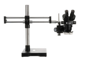
Figure 1. A System 273 (LX Microscopes by UNITRON) Greenough-design stereo microscope with ring light, shown mounted on a roller-bearing boom stand.
The second optical approach is referred to as Galilean or, more commonly, Common Main Objectives (“CMOs”). CMOs generally feature a larger/taller main body, a large CMO attached to the bottom of the main body, and a distinct observation head attached to the top. Objectives and lenses used with CMOs are more highly corrected for color and a flatter, more consistent view across the entire sample — these lenses are referred to as Plan Achromatic or Plan Apochromatic. With the more complicated CMO design comes higher resolution (needed for observation at higher magnification), greater flexibility with attaching accessories, and a heftier price tag over Greenough microscopes. CMOs are also capable of greater zoom ratios, reaching 20:1 or more.
As with simple magnifiers, increased magnification reduces the working distance of stereo microscopes. 80-90mm working distances are common for stereo microscopes with 1x objectives, and that distance with shrink with higher magnification lenses. As with Greenough stereos, auxiliary or reducing lenses (<1.0x magnification) will lower the overall magnification, increase the field of view, and increase the working distance. If manual work or the use of tools are required, working distance and reducing lenses may be quite important to consider.
With stereo microscopes, options for lighting increase beyond that which are typically used with magnifiers. Ring lights (attach to the bottom of the stereo microscope body or objective) are very common and provide even illumination of the sample. Traditional ring lights use fluorescent tubes as the light source, and newer ring lights feature LED lights with variable intensity. For applications where more intense and/or directional illumination is required, “goose neck” lights may be used, and these may be powered by halogen or LED light sources, have variable intensity, and give the user the ability to adjust the angle of the light.
Say ‘Cheese’
After magnification, zoom capability, proper lighting and ESD coating, the next step is to improve or enhance observation, documentation and comparison – essentially ‘workflow’. Such capability is especially valued in contract manufacturing, inspection and repair. In the past, film-based cameras were used for documentation, but that was the extent of the benefit. With video and now digital cameras, inspection can be facilitated with observation of the sample on monitors. Pictures (images) can be readily taken and saved for documentation purposes. Digital images can also be aligned side-by-side for comparison, and enable measurement and annotation directly on the image.
A digital camera may be readily attached to a stereo microscope provided the stereo already has a camera or trinocular port – all that is needed is a camera adapter. Different trinocular ports have different dimensions, and cameras have different sized sensors, so ask the microscope manufacturer for guidance in selecting the correct adapter for both the camera and microscope. If the stereo microscope doesn’t have a trinocular port, an eyepiece camera is a good option. These are designed to replace an eyepiece, and fit right into the eye tube – the camera and eyepiece can be swapped as needed for the purpose.
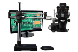
Figure 2. A traditional ESD-safe, true trinocular stereo microscope shown with attached high definition camera and monitor (System 373 from LX Microscopes by UNITRON).
In a traditional trinocular stereo microscope, light from one eyepiece will be directed to the camera for imaging, thus resulting in only one usable eyepiece while imaging. Some stereo microscopes, however, allow continued use of both eyepieces, even while imaging. These are often referred to as “true trinocular” stereo microscopes, such as the System 373 from LUXO Microscopes by UNITRON.
A New Age of Inspection
So why even have eyepieces on a stereo microscope? Just go digital.
Besides taking pictures, digital inspection systems are focused on making inspection easier, efficient and more repeatable. Along with a built-in camera, these systems deliver a plethora of features and functions all designed to accelerate workflow, increase reproducibility, and improve product quality.
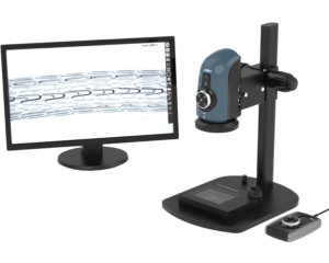
Figure 3. Fully digital inspection systems often include calibrated zoom, live video display on large monitors, on-board software, and image capture directly to removable storage media. [OMNI by Ash Technologies]
These features include measurement applications with automatic edge detection capability, which ensures highly reproducible and repeatable measurements from user to user, sample to sample, and day to day. Other rapid inspection applications include graticules, where go/no-go on-screen templates can define tolerance limits for rapid qualitative analysis. This is particularly advantageous for routine inspection processes where an efficient go/no-go verification check replaces the traditional time-consuming measurement checks. For inspection processes that compare samples to a master reference image, digital inspection applications such as side-by-side and overlay image comparisons, allow samples to be easily and rapidly visually compared to a stored master image on-screen.
Quality control is essential in industry and inspection systems, and digital inspections systems should have calibration traceable to an industry standard, i.e. ISO 17025. Reproducibility of inspection is further strengthened through the ability to save and recall standardized light and camera settings, and by setting limits on user privileges for even greater traceability and control of operational tasks of users with different skill levels.
Optically, digital inspection systems offer a much larger field of view than can be seen or imaged using a traditional stereo microscope. This is done by matching the objective lens to the camera sensor, thus maximizing the resolution in the resulting image, and exploiting the large diameter of the objective for a wide field of view. Another benefit of digital systems is the large magnification range which allows users greater flexibility than traditional optical systems.
Additionally, digital systems reduce neck, back and eyestrain by showing the image on a large screen, allowing for greater adaptability for multiple users plus greater ergonomics through a more natural and comfortable operating position. The ergonomicity of digital microscope systems makes them especially advantageous for high sample throughput inspection processes.
Stand-alone digital inspection and measurement systems like the Omni from Ash Technologies remove non-value add steps from inspection processes and offer a wide range of capabilities helping customers to improve workflow efficiency and quality control.
Digital inspection systems may cost more than traditional stereos, but the benefits in automation, efficiency and reproducibility may make that a trade-off worth considering.